EZE SHORING - CALCULATE WHAT YOU NEED

How to put EZE Shoring together

Assembly

EZE Shoring is a versatile lightweight, high performance composite shoring system, ideal for reducing manual handling injuries. For use in the construction sector when either hand digging or using a mini excavator, to form a trench in soils that are self supporting.

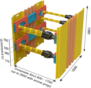
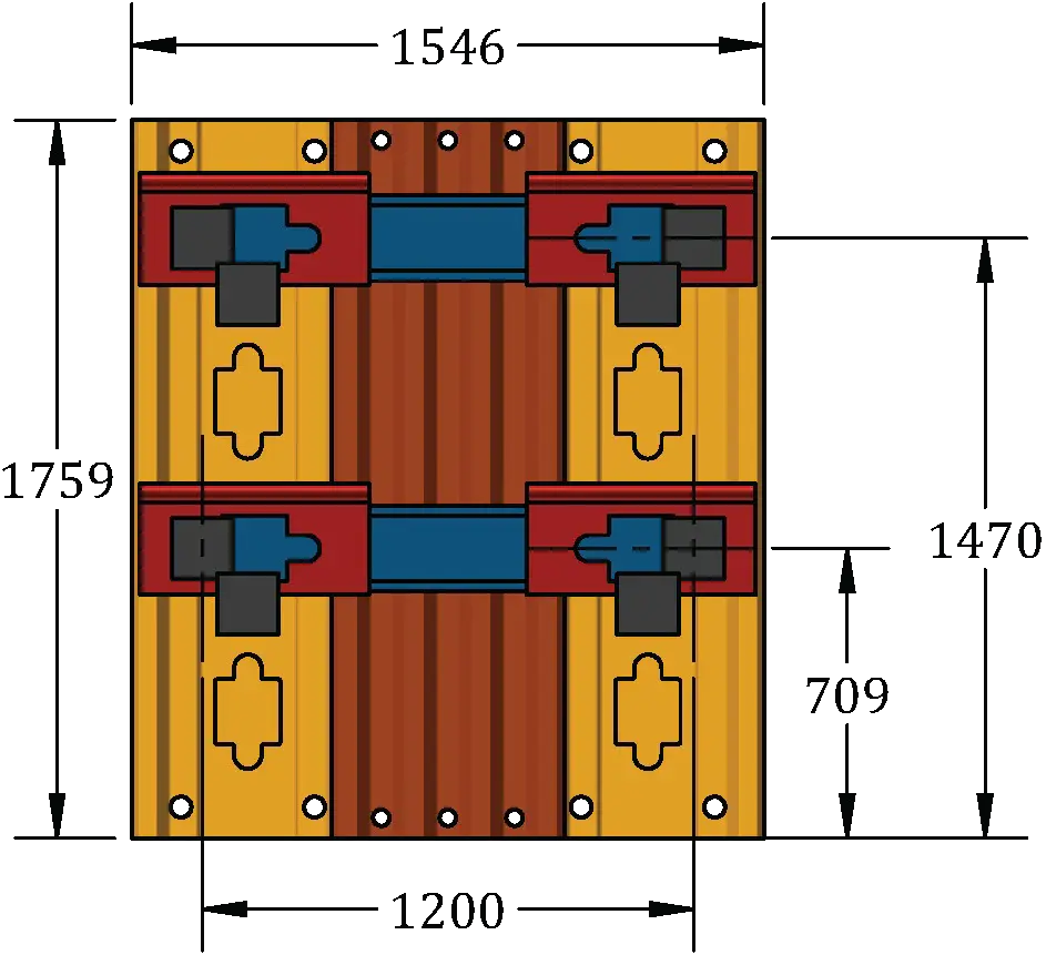
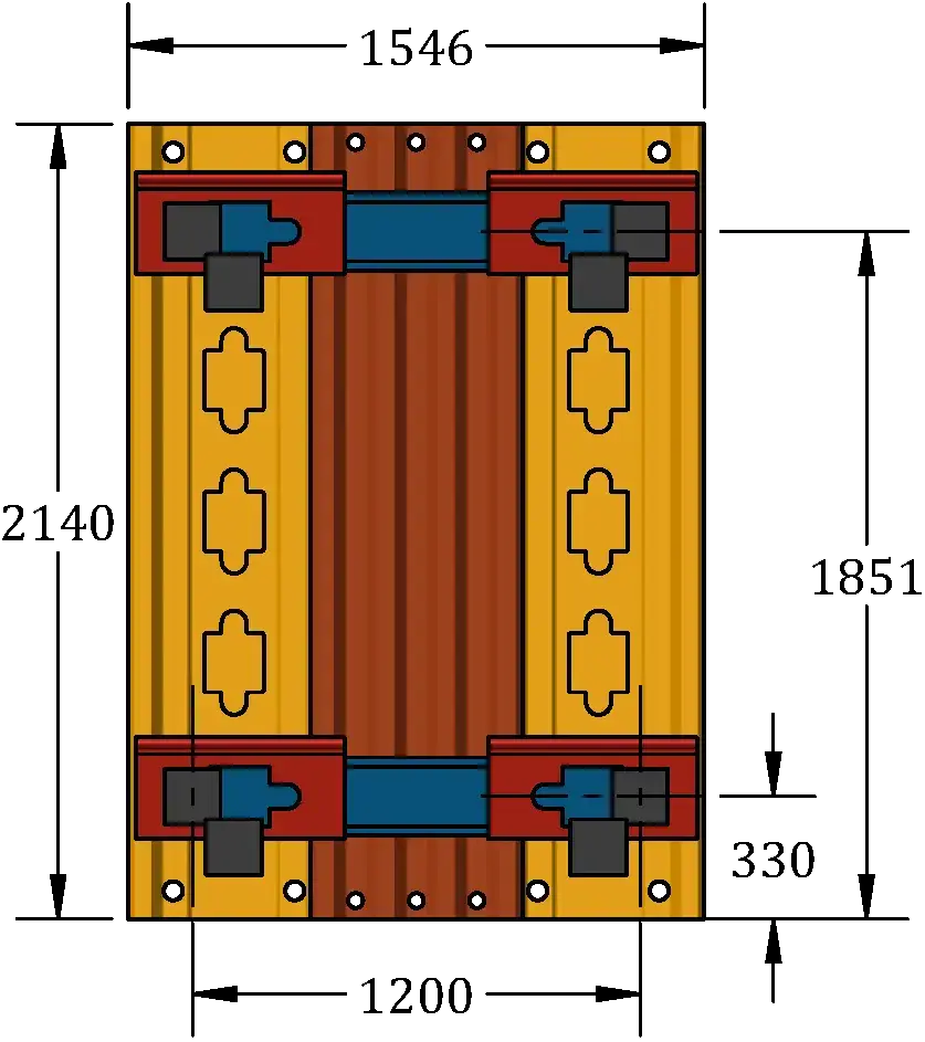
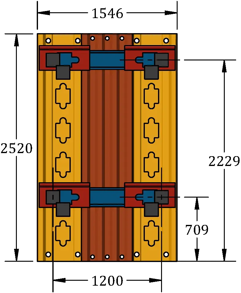
The high performance composite HUBshore system provides shoring solutions for excavation depths from shallow depths – 620mm up to 2500mm – incorporating EZE Strut to support trench widths ranging from 600 mm to 1750 mm. (Up to 2500 mm with a metallic prop).

Always inspect the products for accidental damage prior to use. Always ensure all struts are correctly inserted prior to use. Do not allow personnel within the trench whilst the excavator is digging. Ensure all personnel are well clear of its operation.

Where ever possible only access and work in the trench between supported HUBshore piles. Never enter via ends/faces of an unsupported excavation.

Always work from a position of safety. Avoid, working above on an unsupported edge, an unprotected edge or under a suspended load.

Always ensure operatives are safely out of the excavation before removal of units. (Reversal of the installation)

Do not overload the EZE Struts beyond their stated safe working range. Ensure when in their final positions, the piles sits square and vertical with continuous contact against the trench wall.

When inside the trench, operatives should continually monitor the walls for change of conditions such as excessive movement or cracks and water seepage.

Figure 1: EZE Hub Pile
Figure 2: Hub Board – sub assembly

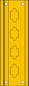
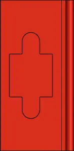
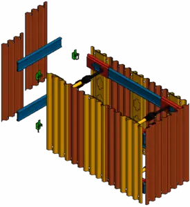
Adjust the EZE Struts to the approximate required width of the trench. Stand up two EZE HUB piles. Insert both ends of the strut into the EZE HUB pile recess with the corner of the strut base plate upright.

Figure 3
Rotate the EZE Strut through 45° to locate and lock inside the EZE Hub pile.
Figure 4
Slide the EZE Strut down into position at the bottom of the slot.
Figure 5 Figure 5A
For each EZE Hub pile sub assembly repeat for the lower strut. If the excavation is to be longer than 1.5m, the second pair of hub piles should have the struts placed as per figure 5A.
Figure 6: EZE Slider
Figure 7: EZE Waler
Figure 8

Position two EZE Sliders onto the end of each EZE Waler.
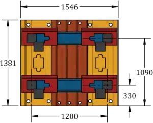
Figure 9
Excavate the trench to the required depth and width. Excavate the ends and batter to a safe angle. Ensure the trench excavation is of suitable length for the ‘to be installed’ system.

Figure 10

Lift the EZE Hub pile sub assembly and position at the top of the battered end of the excavation – 2 persons required. With one person either side of the excavation, lower the sub assembly into position.

Figure 11
Operators should be a safe distance from excavation edge, ensure operatives are always in line with the assembly.
Figure 12
Lift the second EZE Hub pile assembly and place at a distance 500mm apart from the first. Position 2 is approx. 1100mm from the bottom of the battered end.
Figure 13
Repeat for the 3rd EZE Hub pile assembly, installation is from the opposite end of the excavation.
Figure 14
Ensure a distance of 3000mm is maintained between the outside of the EZE Hub pile sub-assemblies. Lower the access ladder into the excavation. Secure the ladder to the EZE Hub pile. Once everything is secured, enter the excavation via the ladder. Lightly tighten the EZE Hub pile struts in the 1st two pairs of boards.
Figure 15: EZE Infill Pile
Figure 16
Lower the EZE Waler assembly down to the operative in the excavation, these rest on the top of the EZE Hub assembly. Insert struts into the EZE Sliders and move the slider over the second pair of EZE Hub piles.
Figure 17
Insert the EZE Infill pile behind the waler on both sides. Remove EZE Struts from 2nd pair of EZE Hub piles to give maximum open working area – Fig 16.
Figure 18
Move the sliders approximately a further 600mm to allow the next pair of EZE Infill piles to be inserted. Note sequence may vary slightly depending upon the installed length of the system.
Figure 19
Move slider to the next position (dependant upon system length) and insert the next EZE Infill piles.
Figure 20
Repeat until all GRP sheets are installed. Tighten the water struts in their final position, ensuring that the maximum spacing between the water struts does not exceed 1700mm. Tighten the EZE Hub pile struts to secure the excavation.
Disassembly
Disassemble in reverse order from figure 20. Never enter an unsupported trench, backfilling must be done from ground level.